
Appiko
Solar or other cable based fences are widely used in the prevention of human elephant conflict, but they are often subject to damage by elephants as you can see in the above video. While it is difficult to prevent elephants from attempting to break the fence, it is entirely possible to monitor the fence status remotely, and get an immediate warning whenever a fence breach is in progress. In such a case, sensors placed on the fence’s pole can sense when there is pushing, shaking or bending of the pole. This information is used to send an alert with long range wireless communication. When an alert is received by the Forest Department, quick response teams can be sent to chase back the elephant and repair the fence before it gets breached further. We propose EleSense - a low cost scalable early warning system placed on fences around the human settlements in the regions affected by HEC.
The tech being developed is completely open source, which means anyone can take the designs, modify if necessary and replicate for their area. We successfully conducted an initial field test of this technology in the Bandipur Tiger Reserve and will be implementing a pilot project of installing our sensors for more than 2 km at the same location. This work was supported by IUCN as part of the European Union funded CITES-MIKE project ”Asia Wildlife Law Enforcement and Demand Management Project: MIKE Programme Sub-regional Support in South Asia and Southeast Asia”.

Tech Overview
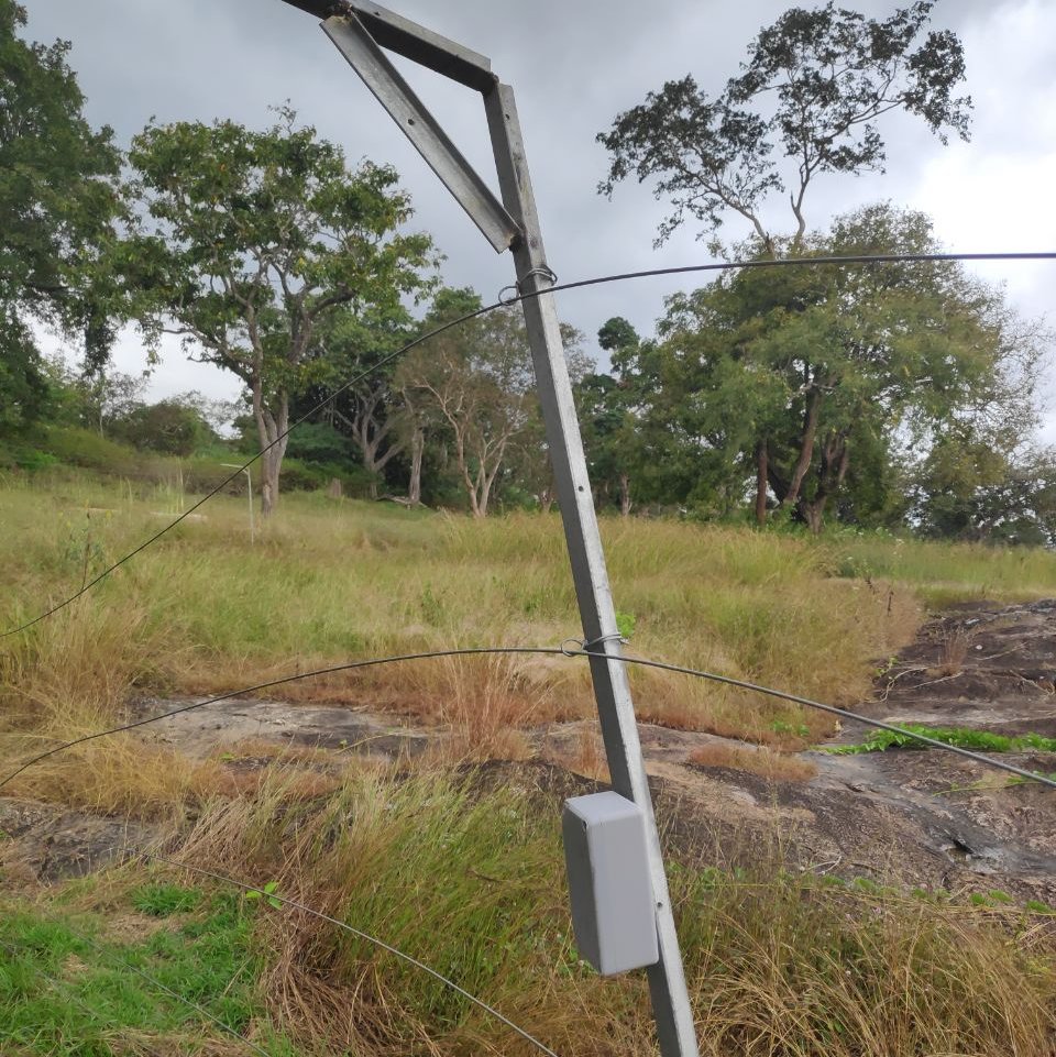
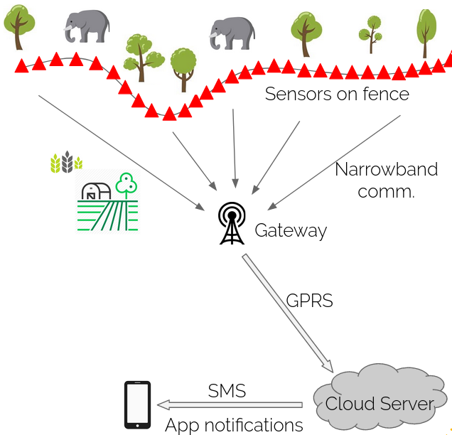
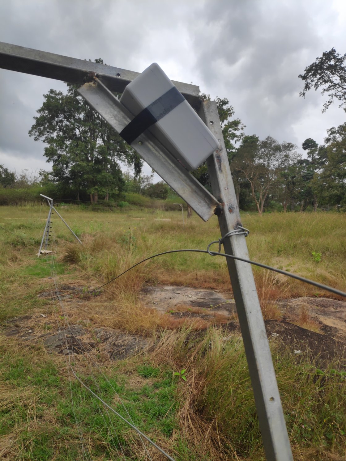
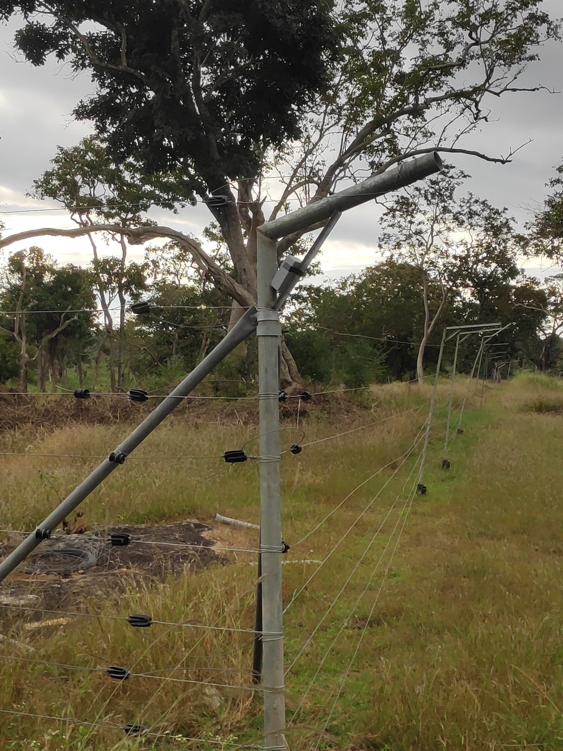
In this project sensor nodes are placed securely on the poles of the solar electric fences around forest reserves as you can see in the image above. These sensors send a signal whenever the pole’s angle with respect to the ground is changed significantly. This can be due to animals pushing at and trying to cross the fence, or similar behavior by people trying to vandalize it. The signal that is sent when this happens can alert the authorities of this, and a quick response can be made. All the sensors in the radius of 2-3 multiple km send a warning wirelessly to a gateway on a tower using narrow-band communication. The gateway then forwards this information over to a central server using the mobile network. The authorized stakeholders can then receive a notification of the location of the source of the alert over SMS and a cross platform mobile app. Additionally they can view the log of alerts and the current status on this mobile app. The image below illustrates this.
Firmware
This section will give an overview of firmware for the project. This contains an overview of both nodes and gateways. Firmware for both nodes and gateways works on state machine implementation. In a state machine, the given system will always be in a pre-defined state and switching between these states is dictated by strictly defined logic. Only if given conditions are satisfied, the system can change the state and system will change the state definitely.
Node Unit:
Node units will be kept along the perimeter. The purpose of these nodes is to sense if a perimeter is being breached and send a notification to the gateway if it is.
States:
There are three possible states in which a given node unit can be at any point in time.
1. Deployment
2. Sensing
3. Maintenance
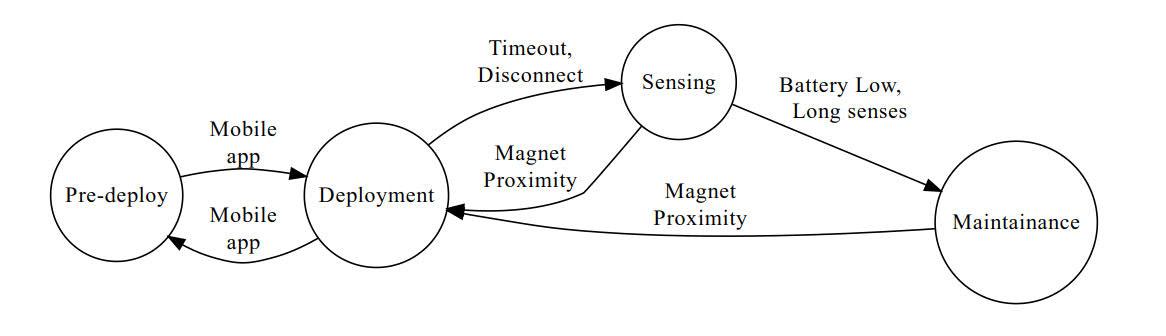
The pre-deployment state is used when the unit is shipped or its deployed location is changed. State machine diagram of this system is as follow:
Pre-Deploy:
All the nodes will be in this state as they are ready to be deployed. In this state, the device will be ready to connect to a mobile device using Bluetooth application. Once connected, the user has to set a device to ‘deployed’ state.
Deployment:
In this state, a device will wait for 15 minutes before it goes to a Sensing state if a disconnect event doesn’t happen. Once the device is set to ‘deployed’ state by a user, it’ll start transmitting current orientation which is needed for the deployment personal to see on the mobile app for proper alignment.
Sensing:
From a deployment state device comes to sensing state either by timeout event or by Bluetooth disconnect event. In sensing state device will check it’s accelerometer values every second. If a device is tilted more than a threshold angle, the device will send an alert packet over RF link. If the device gets stuck at a certain angle, the device will keep sending tilt notification for the first 5 minutes. After the first five minutes, the device will switch to the maintenance state. Also, the device will check the battery level every 5 minutes. If the battery level is lesser than the pre-defined threshold, the device will go in a maintenance state. In sensing state, a node device will also send ‘Alive’ signal over RF link once every hour, to represent the device is online. When a device is in this state, most of the time device will be in sleep mode. For every 1s sensing, it’ll wakeup for 2ms.
Maintenance:
In this state, the node device sends the notification message to relay the need for maintenance. In maintenance state device sends a notification every 6 hours with battery level and current accelerometer values. In this state, the device will wake up once in a 6hrs to send maintenance signal and for the rest of a time device will be in a sleep state.
From sensing or maintenance state, the device can go to the deployment state by bringing any magnet close to the device.
Gateway unit:
A gateway unit is a simple translator between an RF link and a GSM network. At the gateway end, the radio will always be in receiving mode. Once the gateway receives the packet over the RF link, it forwards that to the server over a GSM network.
RF Link:
The RF link is a simple transmitter-receiver radio communication link over the ISM RF band. In RF link, node devices will have the transmitter unit in it which will transmit the package over a frequency in the ISM band. And a gateway device will have a receiver unit that will receive the package.
A package might contain various kinds of information related to transmitting nodes, like maintenance data, sensing data, deployment status. Appiko’s RF packet format can be viewed at the following link:
https://docs.appiko.org/fence-monitor.html
The different types of payload packets are as follows:
Packet type Payload
Maintenance: Data about battery percent and the current sensor value
Sensing: The current reading of a sensor
Alive: Empty packet to signify that unit is alive
Maintenance: Data about battery percent and the current sensor value
Sensing: The current reading of a sensor
Alive: Empty packet to signify that unit is alive
The code for the firmware can be found at
Receiver at the Gateway: https://github.com/Appiko/nrf5x-firmware/tree/rf_comm/application/rf_data_rx
Node: https://github.com/Appiko/nrf5x-firmware/tree/rf_comm/application/KXTJ3_testing
Server
The server is an important part of this project. It handles everything after receiving data from the GSM unit on the gateway; from providing a database service where the GSM can send data to be stored, to the alerting systems which help us in sending push notifications to the mobile app.
What it does:
- Open a Hasura instance
- Check for dead nodes/gateways every x minute(s). As of now we’ve set this to 10 minutes.
- Send alerts as push notifications to the mobile app
Gateway reception
The nodes send alert or alive signals to the gateway over RF and the GSM module on the gateway transmits the same to the single Hasura GraphQL endpoint on the server. GraphQL allows us to perform database operations like updating the alive/alert tables by editing the query (the body) of the HTTP(s) requests accordingly.
Hasura Instance
Hasura is an open source project offering a GraphQL layer for the PostgreSQL database.
As PostgreSQL is a Relational Database Management System, we have tables for the nodes, gateways on the field and other tables to keep track of all the alerts / alive signals received from the gateway.
The GraphQL layer, allows us to perform CRUD (Create, Read, Update, and Delete) operations on the PostgreSQL database easily by making requests to the HTTP(S) endpoints.
Check for dead nodes/gateways
The server has two scripts running as cron jobs, which check for dead nodes every minute, and dead gateways every ten minutes. The scripts call a PostgreSQL stored procedure which returns a list of dead nodes/gateways. If the server finds any dead nodes/gateways, a push notification is sent to the mobile app. If this happens repeatedly the older notification is updated, instead of showing hundreds of cards on the notification panel.
Send alerts as push notifications
We use Firebase Cloud Messaging(FCM) as our notification service and alerts come to the Hasura endpoint whenever there’s a breach on the field, Hasura also comes with a built-in alerting system; using which we can call a function on the server to send the push notification.
When the function is called, it sends a push notification on the mobile phone which has subscribed to that particular FCM deployment topic.
Database
Database tables can be viewed at the following link: https://docs.appiko.org/fence-monitor.html
Stored procedures (Functions)
1. getdeadgateways
Updates the alive columns of the gateways (sets to false if no alive signal from the node in the last 10 minutes), using the checkgateways function using the data from the alive_gateway table, and returns the list of dead gateways.
2. getdeadnodes
Updates the alive columns of the nodes (sets to false if no alive signal from the node in the last 60 minutes), using the checknodes function using the data from the alive_node table, and returns the list of dead nodes.
The server code can be found at https://github.com/Appiko/server-functions
App
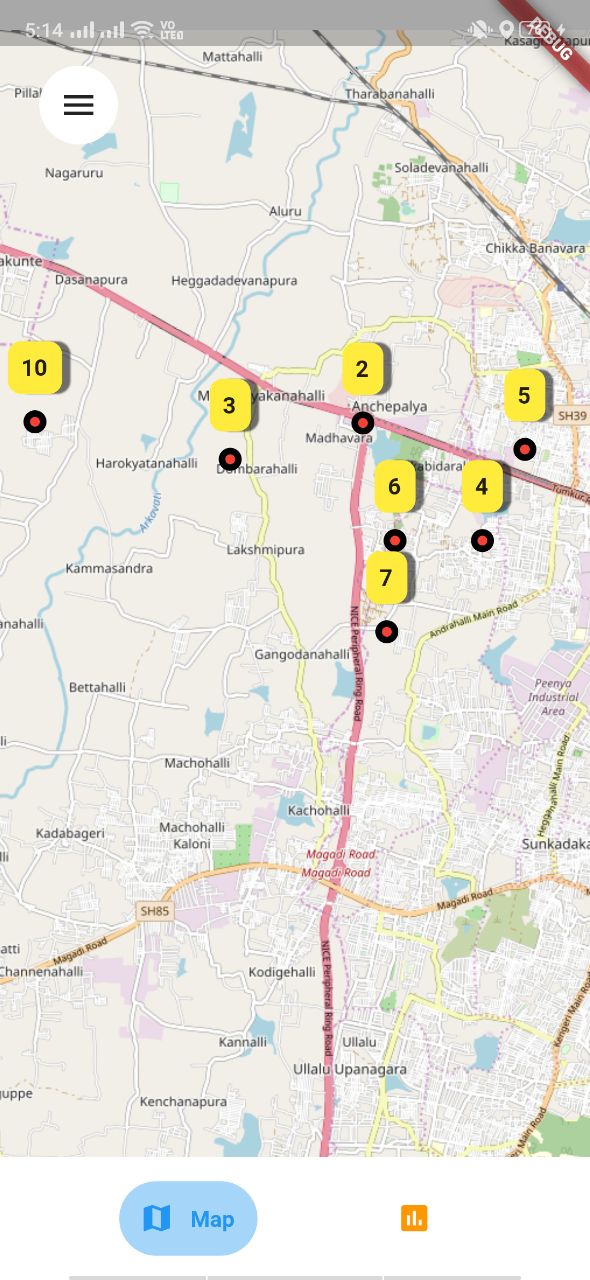
We have an app built with flutter for this project. It helps us visualize the status of the deployed units and also register the devices during deployment. The screenshot above shows the app with a few dummy units deployed.
Features
- Deploy devices
- Show nodes on the map with dead/alive indicators
- Show charts
Deploy Devices
As most of the appiko devices are powered by nRF, we also go to access and work with the Bluetooth.
A node can be deployed from the app, by connecting to it over Bluetooth. The app will receive the MAC address of the board and starts looking for the location with its GPS. Once the location accuracy is below 6m or a minimum of 10m in 30s; the database is updated with relevant information and the device is deployed. In the future we are planning to add an option for Gateway deployment
Show nodes
The app uses mapping service from OpenStreetMaps and it helps us show the markers at the location where the nodes are placed. The markers are colored red or green depending on the status of the node. In the future we are planning to show gateway on the map and the history of the device when any of the markers is tapped.
Charts
Experimental: The app show charts based on all the data collected in the past.
Currently the app supports a chart to show the Date v/s Number of alerts received.
The code for this flutter app can be found at https://github.com/Appiko/senseEle-App
Enclosure
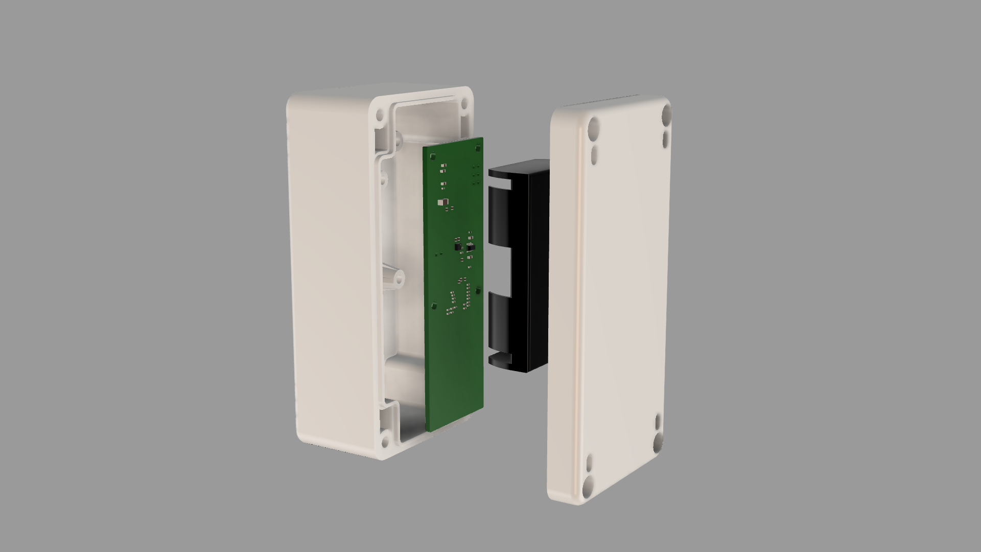
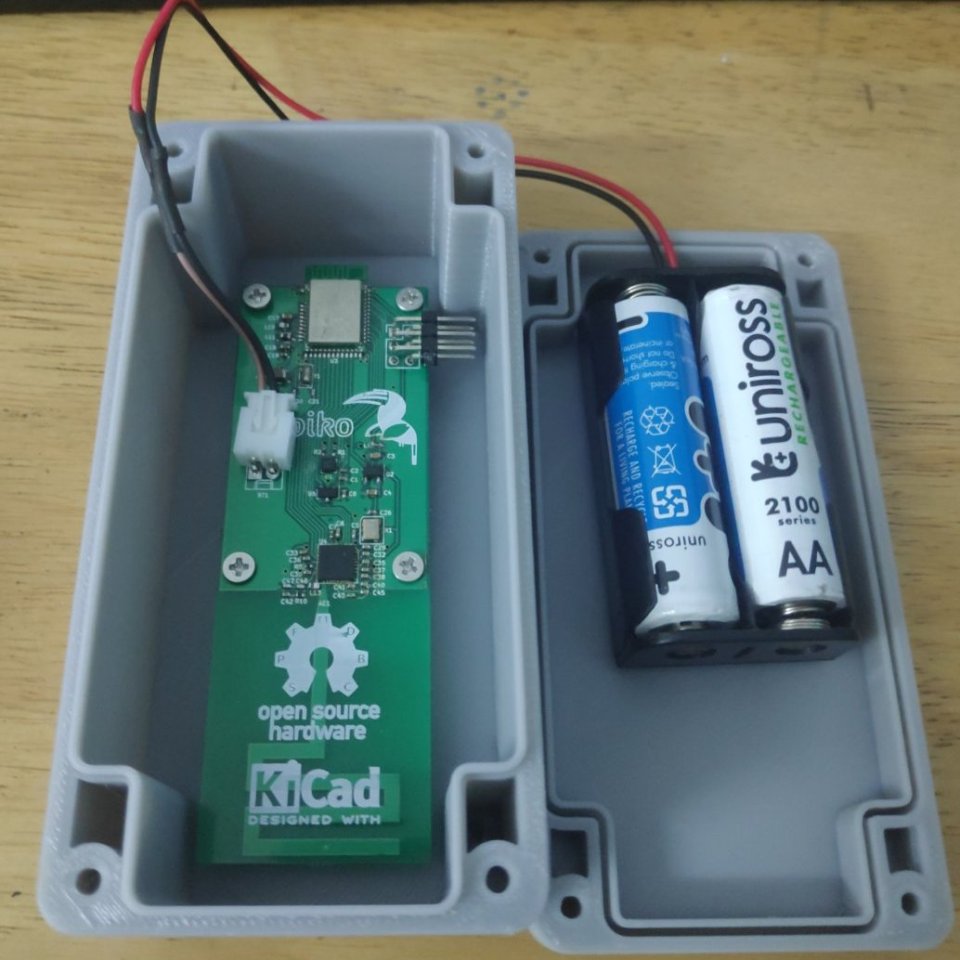
The enclosure has two parts, a cover and a case for holding the electronics. Both the mating parts have slots along the perimeter to house a rubber gasket for water proofing and for providing a secure fit. We have tested that this design can protect the electronics inside even when submerged in water.
Standoffs have been incorporated with suitable draft angle and ribs for added stability and for the ease of injection molding. These standoffs are used to hold the printed circuit board (PCB), on which the dual AA battery holder is soldered. The two mating parts have channels incorporated for the passage of cable ties used to mount the product.
The enclosure design can be found at: https://github.com/Appiko/3D_models/tree/master/senseEle Enclosures
Electronics
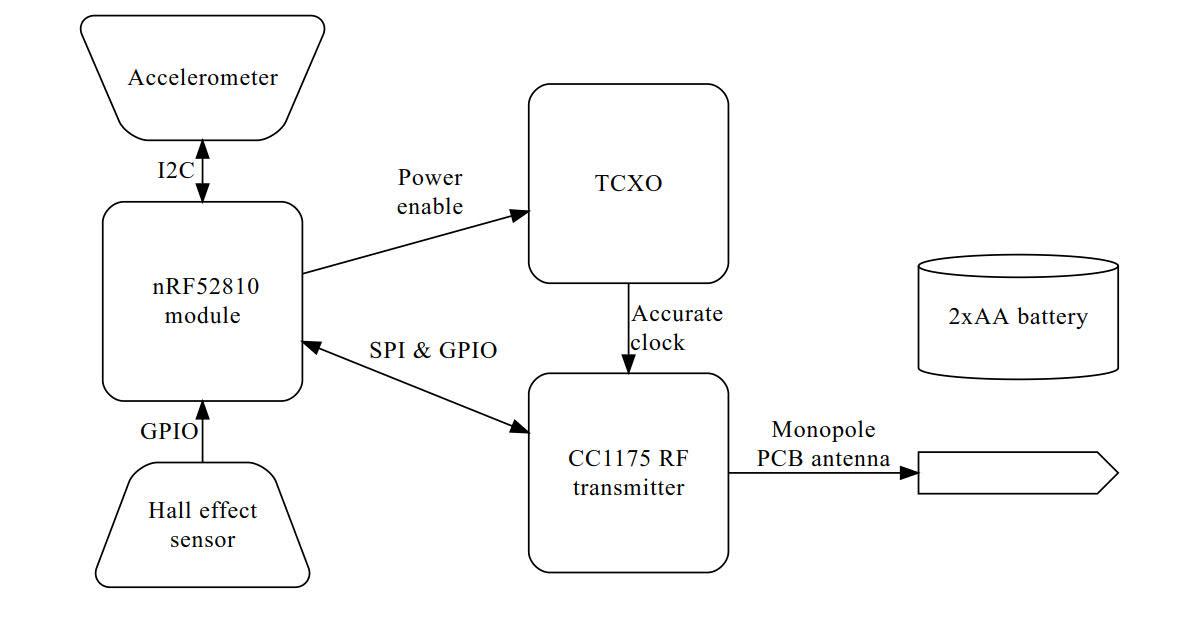
The block diagram of the electronics of the node is as shown in the image above. The primary processing unit used is nRF52810, which is used in the form of mdbt42q module. nRF52810 is a power efficient ARM Cortex M4 based System on Chip (SoC) with a Bluetooth Low Energy (BLE) Radio on the chip.
It interfaces with two sensors, namely KX003-1077 accelerometer and a SI7201 hall effect sensor. The accelerometer is used to measure the tilt of the node and the hall effect sensor senses when a magnet is bought close to the unit.
CC1175 is the transmitter only chip used for the long range communication. The modulation scheme used is Gaussian Frequency Shift Keying (GFSK). Long range communication is achieved by having low receiver bandwidth in the order of a few kHz at the receiver. This also necessitates that the transmitter’s bit rate and frequency deviation is in the order of few hundred Hertz. For ultra narrow band communication, precise timing is needed at both the ends of communication. This creates the need to have a Temperature Compensated Crystal Oscillator (TCXO) which can have an accuracy of about 2 ppm. Since they are power hungry they are only powered on by a linear regulator when they need to provide clock to CC1175.
We have used a monopole antenna designed to work in the 866 MHz ISM band in India. It is made such that the antenna matches the output impedance of the CC1175 RF transmitting pin, thus removing the need to have any matching circuitry. The radiation pattern is that of a doughnut, such that the radiation pattern is maximum parallel to the ground when placed upright. The antenna gain pattern can be seen in the image below.
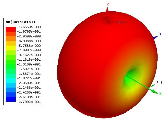
We are extremely grateful to Tej Pochiraju for invaluable hand-holding in getting this antenna in this device. A render of the final PCB can be seen below.
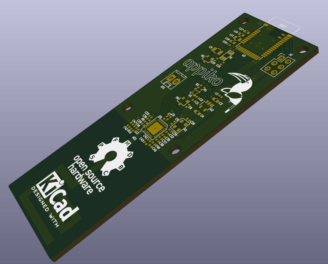
The PCB design for node can be found at https://github.com/Appiko/sense_snap_hw/tree/master/senseEle_PCB_Antenna_rev1
Initial field testing
As mentioned earlier, the deployment for this project would be done at the Bandipur Tiger reserve. We visited the Tiger reserve with the intention of ascertaining from the forest department an ideal location for this pilot project and conducting the test of our sensor prototypes at this location to check for their performance.
The forest department officials suggested installing the fence tilt sensors on the electric fence that is present about 1 km (line of sight) from the premises of the Bandipur offices (base station). This electric fence protects saplings of trees that the forest department grows and is routinely encroached by elephants.
Location scouting
The location of the electric fence is shown approximately with the blue markers on the map below.
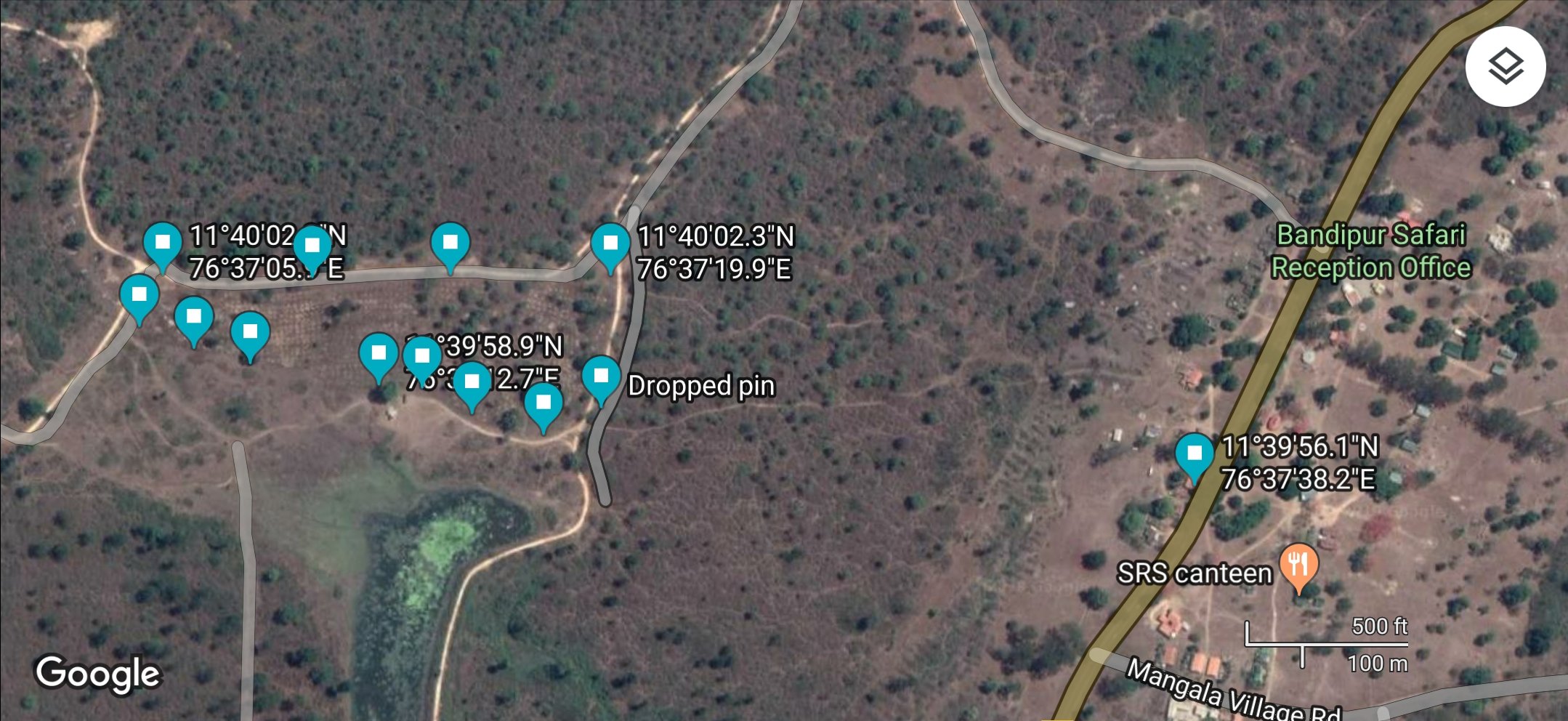
The length of the fence is a bit more than 2 km with poles steel poles holding up the electric wire present every 5-6 m. Right before our visit some poles were damaged by elephants and can be seen in the images below.
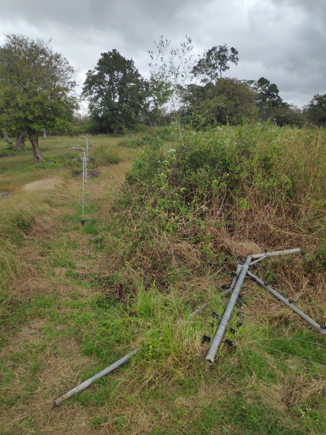
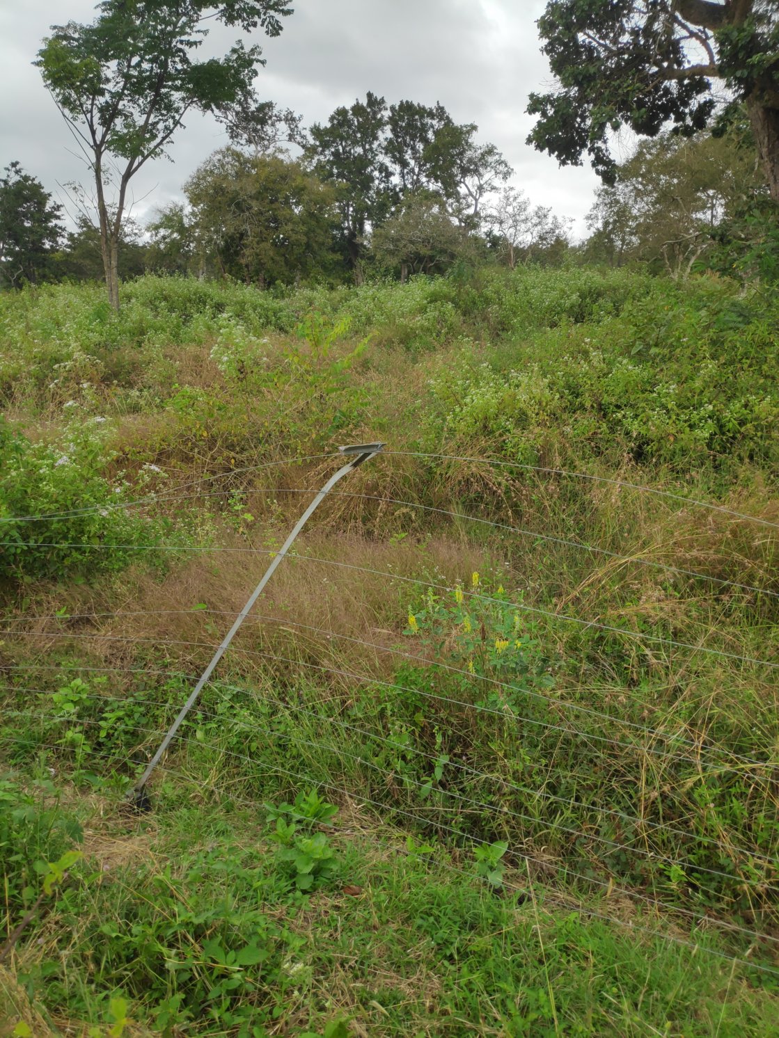
We installed our two of our sensors on two points marked 1 and 2 in the maps above. They were installed at a bent angle so that they kept sending the alert signal.
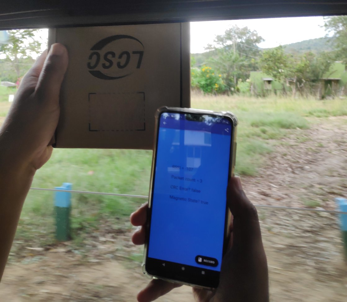
We kept track of the communication from these two units all the way to the base station. Here on the ground we were able to reliably get packets from the sensor at location 2 but unreliably from sensor at location 1. This can be seen in the -107 dBm signal received from the car at the base station.
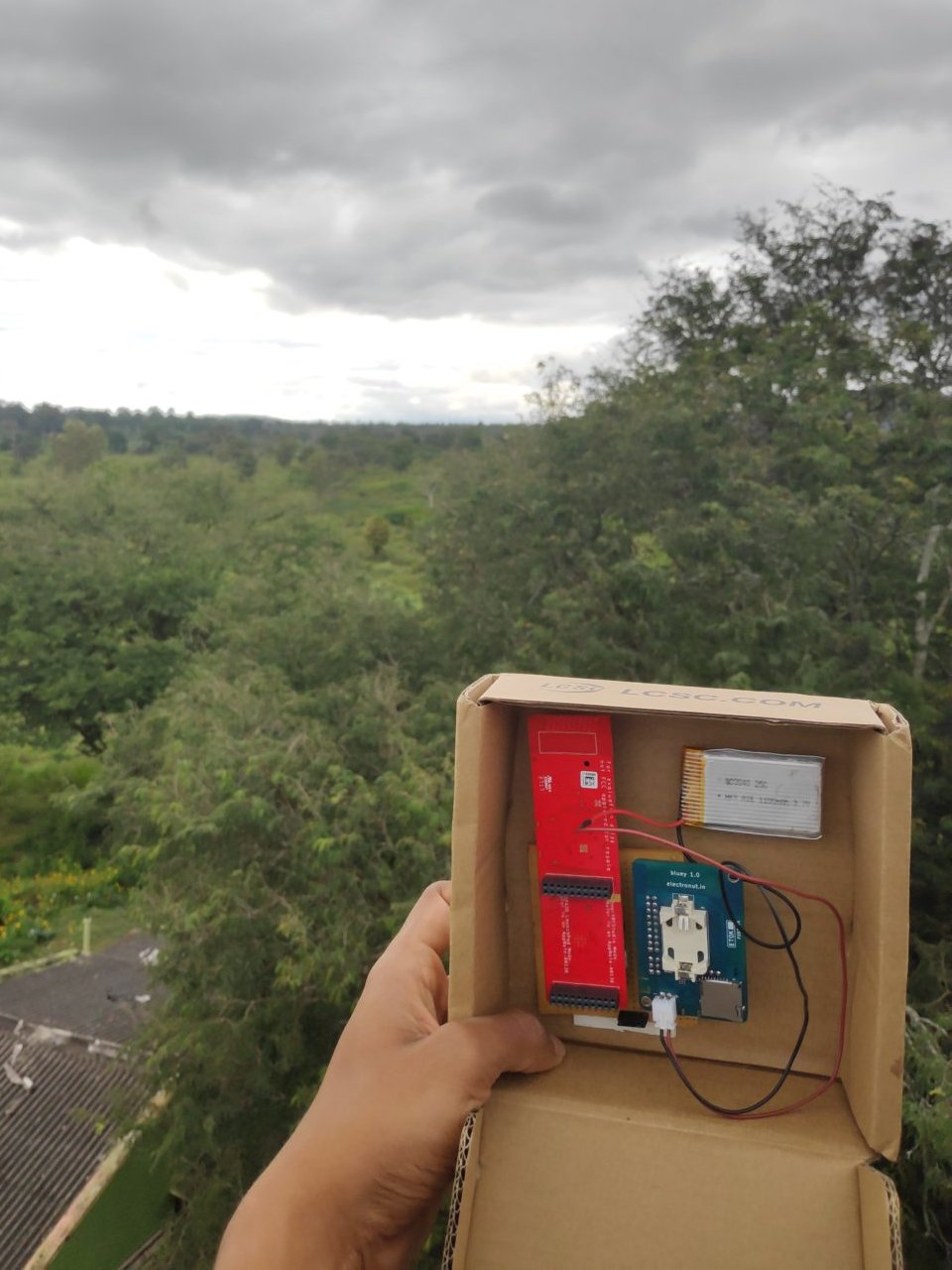
We then tested the communication from the top of an unused tower next to the post office, which is the green marker on the map. From a vantage point at the height of about 16 m, we were able to reliably get packets from both the sensors. The signal strength was about -95 to -100 dBm from both the sensors, which means we have about 20 dBm link budget left. This tower can house the gateway and the building next to it can provide the intermittent mains power supply and house the battery. In the images below you can see Prithvi near the top of the tower and the view from the tower.
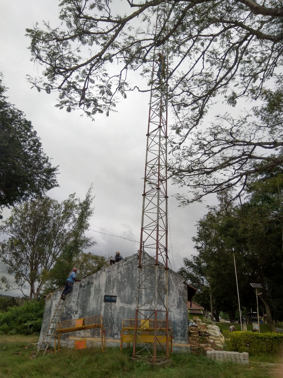
Also there is a BSNL network tower within the base camp to provide mobile connectivity to the gateway. With this we demonstrated that Appiko’s technology is working reliably in the field for the particular electric fence of forest department’s interest. Going ahead we plan to deploy around 150 sensors on this electric fence surrounding the forest department’s plantation.
Appiko creates open source sensor hardware and software for use in wildlife monitoring. Their sensor hardware aims to be user-friendly, low power, app-configurable, and environment-proof. Read more about their field projects and developing products on the Appiko blog.
Add the first post in this thread.